Loading…


Contact Us for Availability
Limited Availability
Please Enquire
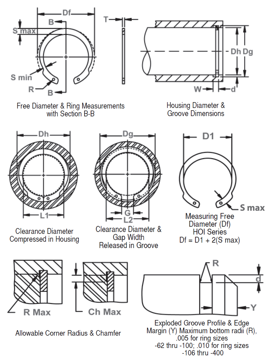
| Housing Diameter | ||
| Dh - Imperial | = | 4 inch |
| Dh - Metric | = | 101.6mm |
| Groove Size | ||
| Dg - Diameter | = | 4.24 inch |
| Diameter Tolerance | = | +.006 to -.006* |
| W - Width | = | 0.12 inch |
| Width Tolerance | = | +.005 to -.000 |
| d - Depth | = | 0.12 inch |
| Circlip Size and Weight | ||
| Df - Free Diameter | = | 4.35 inch |
| Free Diameter Tolerance | = | +.030 to -.020 |
| T - Thickness | = | 0.109 inch |
| Thickness Tolerance | = | 0.003 |
| Weight (1000pcs) lbs | = | 97.4 lbs |
| Clearance Diameter | ||
| L1 - Compressed in Housing | = | 3.29 inch |
| L2 - Released in Groove | = | 3.53 inch |
| Thrust Loads (Square Corner Abutment) | ||
| Pr - Ring Safety Factor of 4 | = | 34713 lbs |
| Pg - Groove Safety Factor of 2 | = | 16900 lbs |
| Maximum Section (Including Lug) | ||
| S max - Maximum Section | = | 0.338 inch |
| Maximum Section Tolerance | = | 0.008 |
| Minimum Section | ||
| S max - Minimum Section | = | 0.161 inch |
| Minimum Section Tolerance | = | 0.008 |
| Hole Diameter | ||
| R - Hole Diameter | = | 0.125 inch |
| Hole Diameter Tolerance | = | +.015 to -.002 |
| Gap Width (Ring in Groove) | ||
| G min - Gap Width | = | 0.93 inch |
| Allowable Corner (Radius and Chamfers) | ||
| R max - Allowable Corner for Radius | = | 0.174 inch |
| Ch max - Allowable Corner for Chamfers | = | 0.108 |
| Maximum Load (with R max or Ch max) | ||
| P"r - Maximum Load | = | 9000 |
| Edge Margin | ||
| Y - Edge Margin | = | 0.36 inch |


Brands
